CM110
FAQs & Troubleshooting |
CM110
Date: 11/03/2019 ID: faqh00000726_000
How do I Create the Cutting Data (Scan to Cut Data) ?
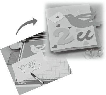
A printed pattern or image or an original hand-drawn illustration can be scanned, converted to cutting lines for cutting/drawing with this machine, then saved as data.
You must update the latest software to use "Recognition mode" depending on your model.
For more information about the software version and update procedure, refer to “Downloads” page.
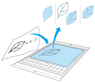
In this tutorial, we will save an illustration drawn on paper as cutting data.
----- Preparing the material -----
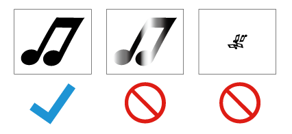
When using the “Scan to Cut Data” mode, use originals like those described below.
- Patterns that are clearly drawn, with no gradation, fading or blurriness
- Not using an extremely intricate design
----- Scanning -----
-
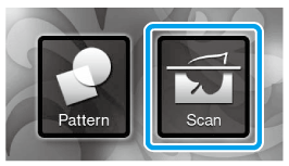
Touch the “Scan” key in the home screen to select the scanning mode.
-
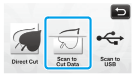
Select “Scan to Cut Data” in the scanning mode selection screen.
>> A message appears. -
Touch
 , select the scanning mode, and then touch the “OK” key.
First, test with grayscale recognition mode. If the desired cutting data is not created, test with color recognition mode.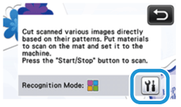
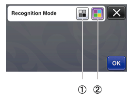
Grayscale recognition mode
The cutting data is created after the illustration is converted to grayscale. Scanning in grayscale recognition mode is most appropriate for illustrations with clear outlines or distinct brightness differences.
Processing is faster with this mode compared with the color recognition mode.
If there are adjacent objects of the same color after an illustration has been converted to grayscale, select the color recognition mode.
Color recognition mode
The cutting data is created without converting the illustration to grayscale. Creating data in this mode may take some time.
* The default color recognition setting is the grayscale recognition mode.
Examples of illustrations appropriate for recognition mode:Examples Recommended recognition mode Outlines that are clear 
Grayscale recognition mode 
- Distinct difference in brightness between
background and illustration- Different brightness of adjacent colors

Similar brightness of adjacent colors 
Color recognition mode The edges of adjacent colors with the same brightness, as shown below, cannot be detected. In this case, use the color recognition mode.
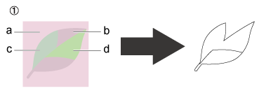
(1) “a” and “b” as well as “c” and “d” have the same brightness.
-
Attach the original to the mat, and then load the mat into the feed slot.
Lightly insert the mat into the feed slot, and press in the operation panel.
Lightly insert the mat so that it aligns with the guides on the left and right sides of the feed slot and is tucked under the feed rollers.
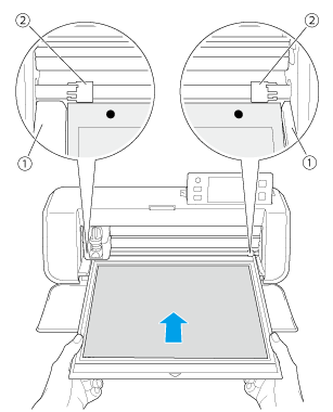
(1) Guides
(2) Feed rollers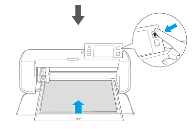
>> The mat is fed in to complete the preparations for cutting.Depending on the machine model, the sizes of mats that can be used will differ. Check the “Maximum Scanning Area” under “Machine Information” in the settings screen.
-
Press the “Start/Stop” button to start scanning.
>> When scanning is finished, the scanned image appears in the screen.
----- Creating Cutting Data -----
The procedure for creating cutting data differs depending on the mode.
Grayscale recognition mode
-
Select the cutting line type in the image editing screen.
The image shape is detected and cutting lines are created based on one of three standards.
For this example, touch
 to create cutting lines using region detection.
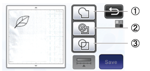
(1) Outline detection
If you wish to cut/draw along the outline of an image, select this option to convert the outline of the image to a cutting line. This is useful for saving as data an illustration drawn for an appliqué.(2) Region detection
Select this option to detect the colored portions of an image as regions and create a cutting line around each region. Cutouts can be created using thick hand-drawn lines, such as borderlines of images or text illustrations. This option allows you to use not only cut-out patterns but the material from which portions are cut out, such as lace.
(3) Line detection (Grayscale recognition mode only)
Select this option to detect the center of lines and convert them to a cutting line. This is useful for detecting patterns consisting of multiple pieces and creating cutting lines for each piece.
Lines thicker than 1.5 mm will not be detected as lines.
Difference in cutting lines depending on detection standard
Example 1(1) Outline detection (2) Region detection (3) Line etection Original


Cutting lines


Finished project
after cutting


Example 2
(1) Outline detection (2) Region detection (3) Line etection Original

Cutting lines


Does not apply since there are no outlines
for each color in the original.Finished project
after cutting

-
Use the touch pen to touch
 and drag it around the screen to trim the cutting lines to be saved as data, and then touch the “Save” key.
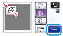
>> Touch to change the minimum object size that will be detected and the conversion threshold.
For details, see Adjusting Image Detection Levels
Color recognition mode
-
In the image trim screen, use the touch pen to drag
 to trim the image to the size to be imported.
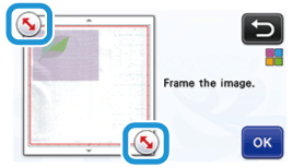
Trimming the image to the desired size can reduce the amount of time required to convert it to cutting data.
-
Touch the “OK” key to confirm the trimmed area.
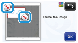
-
Select the detection standard in the image editing screen.
The image shape is detected and cutting lines are created based on one of two standards. For this example, touch to create cutting lines using region detection.
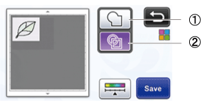
(1) Outline detection
(2) Region detection
Difference in cutting lines depending on detection standard(1) Outline detection (2) Region detection Original 
cutting lines 

Finished project
after cutting

Touch
(1) If the cutting lines were not correctly detected, change the number of colors to be detected. If a color that appears as a single color is detected as separate colors, reduce the number of colors. If adjacent colors with a similar brightness are detected as a single color, increase the number of colors. to change the number of colors and the minimum object size that will be detected.
(2) Small unnecessary patterns (dotted lines, etc.) can be excluded from cutting data.
For details, see Adjusting Image Detection Levels
(3) Touch the “OK” key to apply the settings. When the number of colors is changed, the “OK” key changes to the “Preview” key. After changing the number of colors, touch the “Preview” key to check the results.When making a stamp, for example, the image may not be converted to cutting data if it contains a gradation or areas that are only partially filled with a color.
----- Saving Data -----
-
Select the destination where the data will be saved.
Select the desired location. For this example, select the machine.
>> Touching a key starts saving the data. When the data has been saved, the following message appears.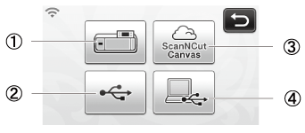
(1) Machine
(2) USB flash drive
(3) CanvasWorkspace (Wireless network models only)This is available only after a connection has been established with CanvasWorkspace.
(4) Computer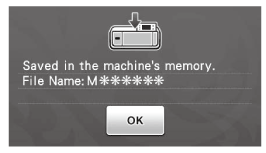
-
Touch the “OK” key to finish saving the data.
>> The destination memory selection screen appears again.
-
Press
 in the operation panel to feed out the mat, and then peel off the original from the mat.
----- Recalling Cutting Data -----
Saved cutting data can be recalled for cutting.
-
Attach the material for cutting to the mat, and then load the mat.
>> For details on attaching the material, see “Attaching & Peeling off the material”.
>> For details on loading the mat, see “Loading and Unloading the mat”.
-
Recall the saved cutting data.
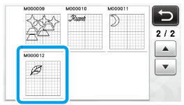
>> A preview of the pattern layout appears.
-
Touch the desired destination, and then select the desired pattern.
-
Edit the cutting data as necessary, and then cut or draw.
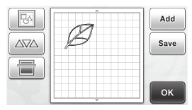
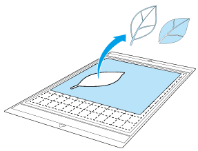
Small spots and unwanted lines created during scanning can be deleted after a scanned image is converted to cutting data.
-
After recalling the cutting data into the pattern layout screen, use the editing functions for selecting the spots to delete.
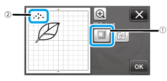
(1) Touch for selecting multiple patterns in the specified area
(2) Unwanted spots and lines -
Specify the area of the unwanted spots, and then touch the “OK” key.
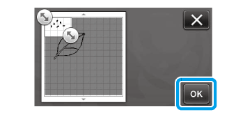
-
Touch
 to delete all of the selected spots.
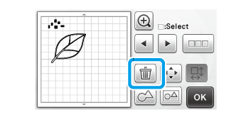
-
After recalling the cutting data into the pattern layout screen, use the editing functions for selecting the spots to delete.
Related FAQs
CM110, CM550DX/ CM550, CM900
If you need further assistance, please contact Brother customer service:
Content Feedback
Please note this form is used for feedback only.